Battery Storage Rack in a BESS

One of the most frequent questions that customer and reps ask us is “Can you model this?” Even though the answer is always a resounding yes – we love a challenge – every rep and customer is still surprised at the broad array of applications that benefit from a Computational Fluid Dynamics (CFD) analysis. This means that a myriad of designs currently in use in different sectors of the building industry could have been improved.

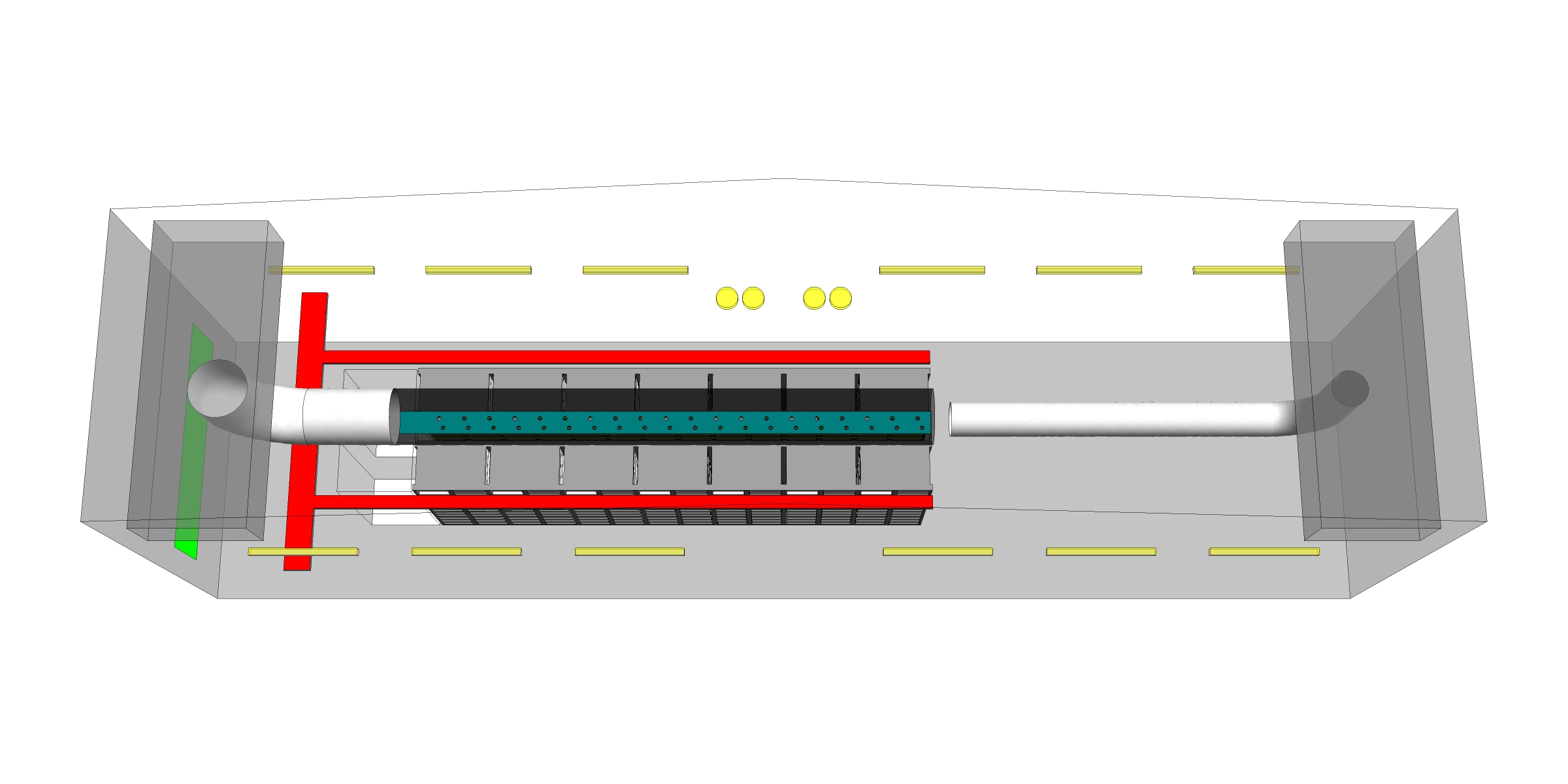
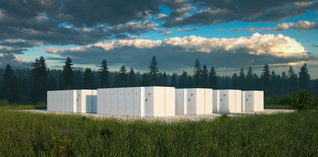
In the summer of 2019, the Price Predict team was commissioned to do a CFD analysis on a project involving a battery energy storage system (BESS). A BESS is a large bank of rechargeable batteries with capacities in the megawatt-hour range that are integrated into an electrical grid and store power for later use. This system can be used either to balance and store electricity generated from fluctuating renewable sources, such as wind and solar power, or to increase the reliability of existing distribution systems by maintaining a steady supply of power when the main grid is down.

The batteries in a BESS generate heat when they are charged and discharged and, therefore, require a cooling system to keep them at an optimal operating temperature. To maximize the storage capacity of a BESS, densely packed banks of batteries are used, which yield heat gains of around 100 BTUH/sq. ft. By comparison, a typical North American office has a thermal load density of 10 to 20 BTUH/sq. ft., while a data center would be around 160 BTUH/sq. ft. Tightly packed arrays of batteries and large thermal loads mean that effectively cooling a BESS can be very challenging.

The Bulwer BESS project in downtown Toronto, ON, is an 8MWh facility built for Toronto Hydro and funded by the Ontario Smart Grid Fund. Madonna Engineering, a local firm, was responsible for designing the HVAC system. The firm engaged the Predict team to help optimize the cooling and air distribution within this facility by leveraging the power of CFD.

A 500 sq. ft. portion of the facility was simulated to keep the project timeline manageable while still providing results useful for the entire space. The modeled space contained 600 battery modules with thermal loads of 50,000 BTUH that required just over 5,000 cfm of air supplied through an overhead fabric duct/diffuser to cool it (see Figure 1 for the CFD model geometry). 

Figure 1: CFD model geometry

The challenging aspect of this design was determining how to get the cold supply air between the batteries in the module to facilitate cooling, since they did not have built-in fans. Although we evaluated many designs throughout the CFD engagement, comparing our initial and final designs is especially enlightening.

The initial design (shown in Figure 2) uses a single row of nozzles discharged in the aisle between two banks of batteries. The final design (shown in Figure 3) uses a duct of a larger diameter than the duct of the initial design and has two rows of nozzles. This provides the same airflow as the initial design and creates a barrier in the aisle, using a cold-aisle containment strategy – an idea borrowed from data centers.

Figure 2: Initial design, which includes a single row of nozzles

Figure 3: Final design, which includes two rows of nozzles and a duct diameter larger than that used in the initial design

Figure 4: Battery temperatures for three different racks show higher temperatures for modules near the top of the battery rack

Figure 5: Battery temperatures of the final design, showing uniform temperatures for all modules

We can assess the results of both designs by looking at the average temperature for each module (see Figures 4 and 5). For our purposes, a module is one horizontal row of batteries, with module 1 being the bottom-most row and module 15 being the top-most row. Additionally, a contour plot that cuts through a cross section of the space shows how the supply air moves through the battery modules for each design (see Figures 6 and 7).

Figure 6: Battery rack air distribution of the initial design, illustrating how supply air is unable to spread to the top of the rack

Figure 7: Battery rack air distribution of the final design, illustrating how containing the cool air improves the air distribution 

For the initial design, the results show that although the modules at the bottom of the rack are cooled effectively, the module temperature increases toward the top of the rack. This is due to the excessive throw of the single-nozzle-row design and to the momentum of the supply air, which is unable to spread to the top modules in such a short distance, thereby bypassing them completely. 

The final design solves this issue by shortening the throw through increasing the number of nozzles (at the same airflow) and by blocking off the ends of the aisle to better contain the cooling air. The results for the final design show a dramatic improvement in air distribution, as evidenced by the uniform module temperatures across the full height of the battery rack.

Although this application is quite different from the types of projects the Predict team optimizes every day, we provided the customer with valuable performance information and design guidance, which highlights the extensive application of CFD modeling. This project is a great example of the forward-thinking nature of Madonna Engineering in leveraging the power of CFD. This application mitigated design risk by ensuring that the batteries operate within their allowable temperatures, which increases battery life and reduces the risk of failures in the field. To learn more about Predict, or if you come across a project you believe is well suited for a CFD analysis, we encourage you to contact us at [email protected].